Wireless Mobile Battery Charger Circuit Pdf
The whole stuff fall in the domain of wireless power transfer WPT or wireless energy transmission. We can either directly connect the cell phone to the main circuit or first charge a rechargeable battery and then use that battery to charge the mobile phone.
Diagram Wireless Mobile Charger Simple Circuit Diagram Full Version Hd Quality Circuit Diagram Diagramofbrain Riciclolio Life It
Simulation using PROTEOUS software is divided into three major task which is schematic construction using ISIS PROTEOUS PCB layout using ARES PROTEOUS and 3D visualizer using Gerber.
Wireless mobile battery charger circuit pdf. It will transmit power to the receiver side. A constant DC voltage is provided by a DC power source and this DC signal is the input to the oscillator circuit. This wireless battery charger is designed to operate at 900 MHz.
A trickle charge circuit can be made using a cheap wall cube as the DC source and a single power resistor to limit the current. And then the rectifier circuit in the receiver will convert the RF microwave signal into DC signal. Presented wireless charger device has the power transfer capability of around 05 W at a maximum distance of 25 cm which is sufficient to charge a regular mobile phone.
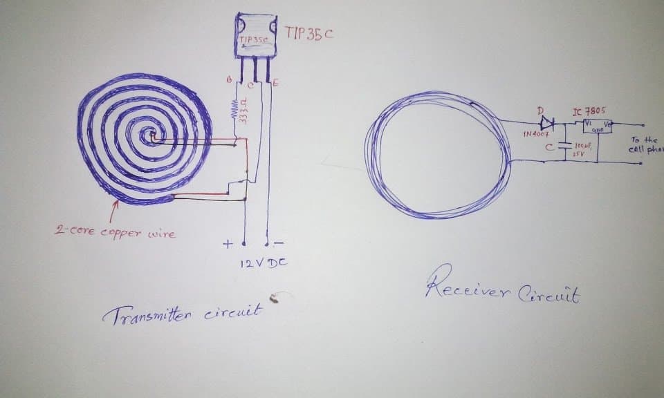
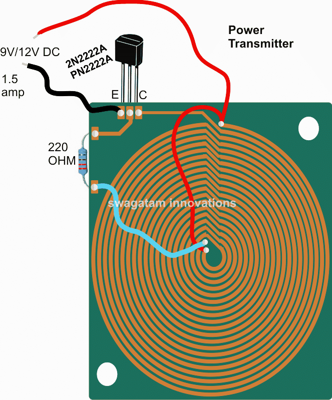
10 Chapter 5 Implementation. The Transmitter section of wireless charger circuit consists of a DC power source oscillator and a transmitter coil. Proteous Simulation The PCB foot-print layout is designed using PROTEOUS software before transferred onto PCB board.
The first circuit is transmitter circuit used to produce voltage. The oscillator circuit has two n channel MOSFETS 4148 diodes and IRF 540. PTU Class 1-6 P RX Out Max from 35W to 50W Cat.
Raisoni College of Engineering Nagpur Department of Electronics and Telecommunication. Wireless Mobile Battery Charger Circuit using MULTISIM Simulation 22. INTRODUCTION There is a basic law in.
The project is meant to charge a low power device quickly and efficiently by. A Wireless Battery Charger for Mobile Device Tarique Salat1 Shilpak Raich2 Supriya Mahto3 and Shilpa Togarwar4 1234 GH. Block diagram of wireless power transfer system In this project supply voltage 12 DC drives oscillator circuit as push-pull driver to operate transmitter coil.
Wireless power transmission mobile charger circuit using inductive coupling is to charge a low power device using wireless power transmission. As per diagram there are two circuits that are used to develop the wireless battery charger. Ni-MH cells are not as tolerant of sustained.
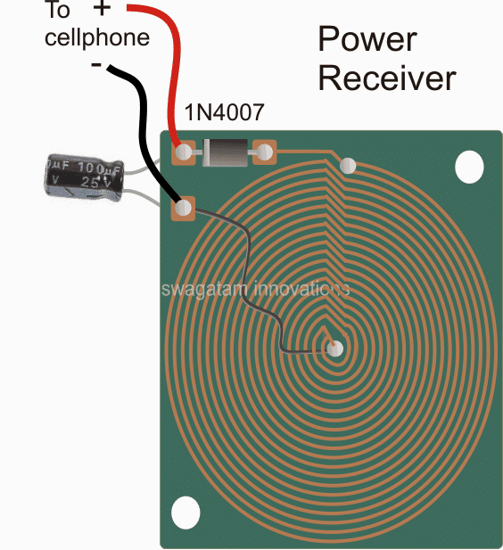
After the DC signal is produced the charging circuit will store the power into the battery. In this post we will learn how to build a wireless cellphone charger circuit for facilitating a cordless cellphone charging without employing a conventional charger. Wireless mobile battery charger circuit pdf To ensure that our content is always up to date with current information best practices and professional advice articles are regularly reviewed by industry experts with extensive experience.
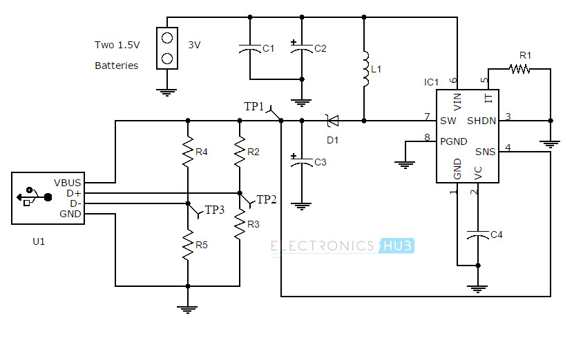
The project Wireless Mobile Charger Circuit Diagram posted here can deliver 271mA at 52V so you charge mobile phone and also can be used to drive low power load such as LED 1 and. In this project a power transmitter acts as the power source. 67 MHz Transmitter Coil Receiver Coil DC Level Stabilizer Charging Battery Fig.
Here is Wireless Mobile Battery Charger Circuit Commercial Kits and Theory. Magnetic induction PRU Category 1-7. The goal of this project is to design a prototype wireless energy charger for low power devices with specific emphasis on mobile phones.
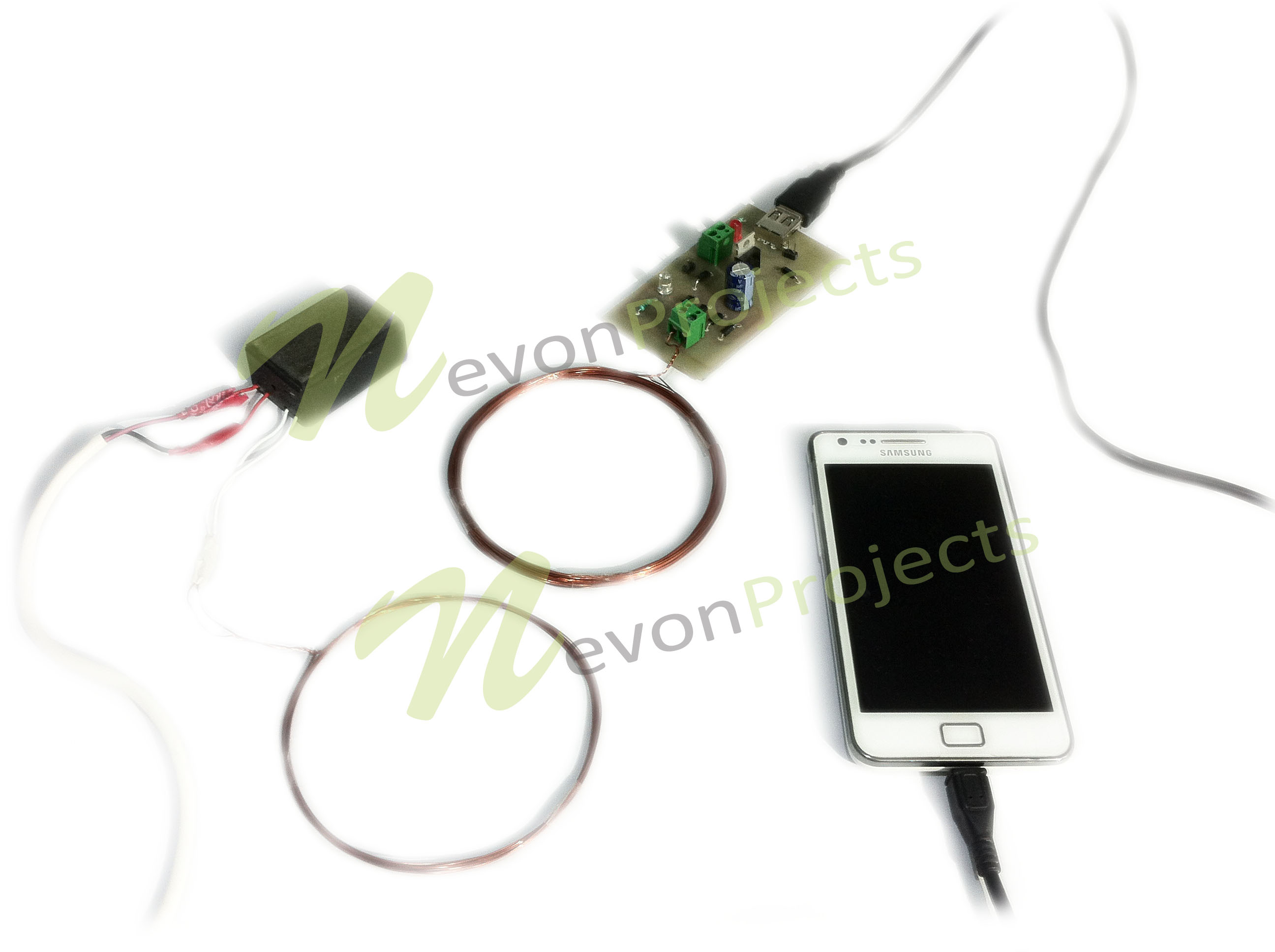
Wearable Mobile phones and tablets Medical Smart home Auto Power tools Leave cables at home and top up batteries. Wireless Mobile Charging is one of the trending topic in the field of electronics thus we also decided to build a Wireless Mobile Charger Circuit Diagram using various commonly available components. 54 Mobile charging after storage of power Once the power is generated it can be used to charge a cell phone.
In our Wireless battery charger we use two circuits. Rizvi College of Engineering Bandra Mumbai. We have to write the guide for all type of readers.
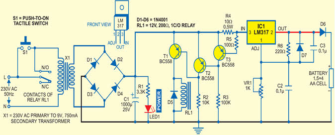
These circuits require only resistors capacitors diodes Voltage regulator copper coils and Transformer. 1 TBD P TX Input Max from 2W to 70W Wireless Power at a Glance 3 Advantages simple efficient safe power scalable mature Key technology challenges shield coil alignment good. Through research and design this prototype will critically address and analyze the major design challenges that bring about longer charging periods of the new inductive wireless charging compared to the old fashioned wired charging method and provide.
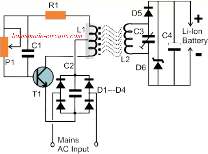
Wireless Mobile Phone Charger Circuit Diagram Pdf Posted by Margaret Byrd Posted on September 1 2017 Wireless charger diagram high cur battery cellphone circuit mobile li ion 100 and international journal of soft computing. The Wireless Mobile Battery Charger System uses one coil. This oscillator converts this DC voltage to a high frequency AC power and is supplied to the transmitting coil.
It is actually quite easy thing. Wireless Mobile Battery Charger Circuit Wireless Power Transfer Circuit Diagram. Considered on September 23 2020 Portable security charger glove goggles driver manual jumper Cable Car Battery Portable Battery Safety Drivers Safety Glasses.
Battery Oscillator Circuit 1. Here is the block diagram of the overall design. Wireless battery charger circuit design is very simple and easy.
The ability to easily charge a Ni-Cd battery in less than 6 hours without any end-of-charge detection method is the primary reason they dominate cheap consumer products such as toys flashlights soldering irons. This is done using charging a resonant coil from AC and then transmitting subsequent power to the resistive load. Then the transmit-ter coil transmits coupling magnetic field by passing frequency at about 167MHz.
In this state. Not all can understand what to do if we start from drawing circuit diagrams. The first one is the transmitter circuit and is used to generate voltage on wireless fashion.
This circuit has oscillator circuit transmitter coil and DC power source. A wireless cellphone charger is a device that charges a compatible cellphone or mobile phone placed close to it through high frequency wireless current transfer without any physical contact.
Usb Mobile Charger Circuit Mobile Phone Travel Charger Mobile Charger Diy Wireless Charger Circuit Diagram

Wireless Mobile Charger Circuit Diagram Engineering Projects

Wireless Cellphone Charger Circuit Homemade Circuit Projects
500 Km Fm Transmitter Circuit Diagram Circuit Diagram Images Fm Transmitters Circuit Diagram Circuit

Wireless Power Transfer Circuit Wireless Mobile Charger Mobile Battery Charger Wireless Wireless Battery Charger

How To Make Portable Battery Charger
Wireless Mobile Charger Circuit Diagram Engineering Projects
Samsung Mobile Charger Circuit Diagram Pdf
Wireless Cellphone Charger Circuit Homemade Circuit Projects
High Current Wireless Battery Charger Circuit Homemade Circuit Projects
Wireless Li Ion Battery Charger Circuit Homemade Circuit Projects
Wireless Charger Design Principle Concept Explained Electronicsbeliever

Wireless Cellphone Charger Circuit Homemade Circuit Projects
Battery Charger Circuit Page 7 Power Supply Circuits Next Gr
Wireless Mobile Charger Circuit Diagram Engineering Projects
Advanced Wireless Mobile Charging Project
Https Www Ijeat Org Wp Content Uploads Papers V7i1 A5198107117 Pdf
High Current Wireless Battery Charger Circuit Electronic Circuit Projects Battery Charger Circuit Wireless Battery Charger Electronics Circuit

Wireless Mobile Charger Circuit Diagram Engineering Projects


Post a Comment for "Wireless Mobile Battery Charger Circuit Pdf"